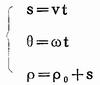
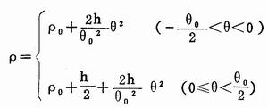
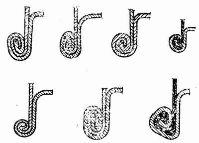
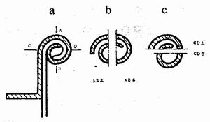
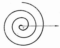
Analysis of the process of round lifting of 200 liter steel drum (2) Tianjin Tiexie Metal Container Committee Wu Tielin 3. Pre-crimping effect and size analysis The pre-crimping process is a process in which the bottom cover is separately processed (without a barrel). This process is the simplest and the easiest to achieve: it has a large effect and determines the quality of the rounded edge of the steel drum. A pre-rolling groove is formed at the edge of the circumference of the bottom cover during the pre-rolling. The filler is injected during the pre-rolling process and evenly rubbed to the edge by centrifugal force. After drying, a sealing ring is formed at the bottom of the pre-rolling groove, and the sealing effect is optimal. Through the mold analysis, we know. The pre-rolled portion of the track is the innermost layer of the rounded edge, which corresponds to the beginning of the flat curl. Its shape and size directly affect the shape and size of the round bead. In theory, the greater the curvature, the better. Due to practical considerations, sufficient packing clearance should be left. Ideally, the maximum distance in the pre-roll (if the arc curve, ie the maximum inner diameter) is 25 mm. The pre-hem of Figure 6 only completes 1-2 segments. For the convenience of analysis, the section 1-2 is a half arc, the diameter is 3b (b is the thickness of the steel plate), the thickness of itself is 1b, the thickness of the barrel is 1b, and the gap of the packing is 1b. The unfolded length is (3b × Ï€) / 2 = 6.75mm (b = 1.25mm). If the pre-roll is omitted, this arc curl with a maximum outer diameter of 5 mm is only done by the free curling section, which is not easy to do. In order to turn the free curling section into a forced crimping section, it is necessary to separately pre-roll with a roller having the largest curvature. 4. Mold manufacturing and repair Designing a reasonable roller curve is very difficult to manufacture and often fails to meet the design requirements. Common processing methods are: 1 rely on sample processing. The accuracy is not high and it is not accurate. The processed rollers are the same, and the effect is good or bad. This backward method has also been widely adopted. 2 Processing with a forming tool. More advanced, due to different process of each factory, the tool processing batch is small and uneconomical. It is best to promote advanced technology in a region or nationwide, using uniform tools to ensure quality and economical simplicity. This method has been adopted by individual manufacturers. The forming method of the forming knife is preferably a digital program controlled wire cutting machine tool, the precision is controlled at l0 μm, and the program is programmed according to the design curve. It can also be processed by photoelectric tracking wire cutting machine, and a reasonable front and rear angle is ground after processing. 3 Old molds used for a period of time, most manufacturers are scrapped. This is too uneconomical. A new process, thermal spraying, should be used. True B mold can be sprayed with nickel-based materials, and has good wear resistance. It can be sprayed once per 1-2 million barrels, and the thickness is 100-200μm without quenching. The effect is very good. 5. Mould drive Designing and manufacturing a reasonable mold does not guarantee the quality of the steel barrel crimping. Another important factor is the mold drive. It controls the speed of the curve forming of each section of the curl (much like the relationship between precision and the depth of the knife and the speed of the cutter), ensuring rapid feed, constant feed, deceleration, and maintaining the shape according to a certain procedure. Rewind and other driving processes. In the process of crimping, there is no feed to the roller. The same requirements. The driving device of the mold includes: manual driving of the screw, cam control drive, hydraulic drive and hydraulic servo system. 1 screw manual drive is a backward drive. The speed of the feed is controlled by the experience of the operator. Physical labor intensity is great. At present, except for a few regions, it has basically been eliminated. 2 cam control drive is a relatively advanced, reasonable drive. The curve of each section of the curling roller and the corresponding deformation speed are reflected by the cam equation. The cam drive schematic is shown in Figure 8. Figure 8 cam drive schematic The cam rotates at a constant speed, and the equation for the uniform feed of the roller is as follows: Solving the equation Ï. - The radius of the base circle, α - coefficient, can be found. The cam rotates at a constant speed, the roller accelerates evenly, and the polar coordinate cam equation is uniformly decelerated: After the cam design is completed, the pressure angle check is performed. The curling cam feed stroke has a pressure angle of less than 30°. The cam profile curve of the equal pressure angle is called the logarithmic spiral. Its equation is Ï=Aeke. The cam drive unit has precise control and high production efficiency and has been widely used in the steel drum manufacturing industry. Its cam equation can be entered into a computer to provide software for the hydraulic servo system. Three parts of the manufacturers have begun to adopt hydraulic drive. It is characterized by a large driving force, and the feed time is controlled by the programmable controller, but the feed speed cannot be adjusted and controlled according to the requirements of the roller curve and the curling deformation. 4 hydraulic servo system, the driving force is provided by hydraulic pressure, and the feed speed is controlled by the servo system. Different sheet thicknesses and different process sizes can be modified at any time and have feedback function. The main control process is: digital program (or cam curve equation) → input computer → digital processing → output to stepper motor → potential adjustment → electro-hydraulic valve → execution cylinder → drive mold (roller). It is the ideal drive. Second, the shape analysis of the rounded edge of the steel drum Since the rounded edge of the steel drum is relatively flat, the outer shape of the rounded edge of the steel drum is various and eclectic. Figure 9 shows the various types of round curls in Europe. As a result of the extrusion setting, the outer shape of the rounded edge can no longer truly reflect the original shape of the forced curling section, and does not reflect the shape of the freely curled section. Simply analyzing the shape of the outline is one-sided. Proper analysis of the shape of the rounded edge should be performed to analyze the shape of each segment of the curve in a complete steel drum round bead. Shape analysis is the basis for designing crimping dies. Shape analysis should also include another important element, the length of the curve. The unfolding length is an important basis for designing the size of the bottom cover of the steel drum, the size of the stamping die and the flange of the barrel. Each segment of a complete rounded edge can be a circular curve or a non-circular curve. Therefore, there are three kinds of curved shapes of the round curl: a circular curved circle, a non-circular round, and a mixed curved round. Figure 9 European various forms of round curling 1. Arc curve round Each segment of the round curl is a circular arc curve. The advantage is that the shape is intuitive, easy to be accepted, and the processing is simple, and the expansion length can be calculated by everyone. Arc curve curling is a widely used curling shape in China, but the curling quality is not optimal. Now analyze the typical arc curve round curl (Figure 10). Figure 10a shows a five-layer circular bead. If you cut from AB, divide the round curl into two left and right halves, and get the picture lOb. The arc curves of the bottom cover AB left and AB right have their own radii. There are two segments of different radii on the left and only one segment on the right. In fact, the number of segments can be divided more, and the curve of the roller for processing these segments can be seen at a glance. If you cut from the CD, divide the round curl into the upper and lower halves to get the figure 10c. Its intuitiveness is as simple as cutting from AB. The selection of the roller curve depends on the combination of the line segments. Figure 10 Typical arc curve round curl analysis The basis of the circular curve rounded shape is the radius of the packing gap and the minimum arc curve. On this basis, the radius and profile size of each segment and the total unfolding size can be determined according to the number of layers. 2. Non-circular curved circle The non-circular curve circle is the curve of each circle of the circle, and it is not the arc curve. In the mold analysis, we have proposed the ideal roller curve. The curvature of its deformed section, from small to large, varies continuously and without curl of equal curvature. The effect is that the tighter the volume, the denser the layer. After continuous exploration, we found an ideal roller curve. Roll up - the ring is larger than a circle, and the distance between the two turns is equal, there is no gap, which can meet the requirements of the ideal roller curve. This is a very useful non-circular curve. So far, no manufacturer in China has adopted a non-circular curve for the rounding of steel drums. Some foreign manufacturers have adopted non-circular curves, but they cannot meet the requirements of our ideal roller curve. This article introduces this ideal curve, which is equivalent to the disclosure of a "patent" that everyone needs. Of course, what we disclose is only the theoretical part. Many of the data are theoretical data. Many practical problems still need to be solved. Since this non-circular curve is applied to the steel barrel crimping process, we call this non-circular curve "steel drum volume." Edge curve". (1) Polar coordinate equation of steel drum curling curve. Steel drum curling curve, Figure 11. In the polar coordinates, there is a point, starting from the center of the pole O, rotating counterclockwise around the pole center O, the distance from the pole center O is getting larger and larger, and the angular velocity is ω. In a certain period of time, the angle of rotation is θ, and θ is called the polar angle of polar coordinates. Corresponding to the polar angle, the distance from the point to the center O is called the pole diameter Ï. The trajectory of the point moving in polar coordinates is the steel barrel curling curve. It has the following characteristics: Figure 11 steel barrel curling curve Distance from 1 point to the center of the heart, with a single value, that is, corresponding to a polar angle θ, only one pole diameter Ïo The 2 pole diameter is proportional to the polar angle Ï = αθ. That is to say, the Î”Ï corresponding to the increase of the same angle Δθ is equal. This ensures that the distance between the two layers of motion trajectories is equal. Ï=αθ is the steel barrel curling curve equation. In the formula, α is a constant, which is determined by the thickness of the steel sheet in the hemming process. If the thickness b of the steel plate is 1.25mm, there is no gap between one layer or one turn (2Ï€), and the thickness (distance) should be two layers 2b, substituting â–³Ï=αΔθ 2b=α2Ï€ α=b/Ï€ Substituting Ï=αθ Ï=bθ/Ï€ List the following table Table 1
Cutting Board Cutting Board,Unbreakable Cutting Board,Vegetable Cutting Board,Eco-Friendly Cutting Board Yangjiang Homelife Industry & Trading Co., Ltd. , https://www.bettyhomelife.com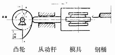
![]()
Analysis of the process of round lifting of 200 liter steel drum (2)
θ
Ï
θ
Ï
0
0
2.25Ï€
2.8125
Ï€/4
0.3125
2.5Ï€
3.125
Ï€/2
0.625
2.75Ï€
3.4375
3Ï€/4
0.9375
3Ï€
3.75
Ï€
1.25
3.25Ï€
4.0625
1.25Ï€
1.5625
3.5Ï€
4.375
1.5Ï€
1.875
3.75Ï€
4.6875
2Ï€
2.5
4Ï€
5