(3) Laminated cushioning materials: (4) Recommended Laminating Method (Flow): 5. Drilling and Drilling: As rigid-flexible printed boards use rigid and flexible materials, it is easy to generate a large amount of drilling pollution. Therefore, the choice of drilling materials and drilling process parameters are very important. It is well-known that the formation of drilling contamination in PCB holes is due to the fact that the resin in the PCB is melted due to the high temperature during drilling. Therefore, when selecting materials, aluminum foil and backing plate with good heat dissipation performance should be selected (should also take into account The surface roughness of the aluminum sheet and the material of the backing plate, such as Cimatec's CIM-Alu 1001 and CIMWOOD SD-27, can well balance the performance of several people.) At the same time, before drilling, the rigid flexible printed board can be drilled at a low temperature such as a refrigerator for several hours before being drilled. A higher drilling speed and feed rate should be used when drilling, and it is better to maintain the air-conditioning temperature. Drill holes to reduce the generation of dirt. 6, outer imaging and graphic plating: Rigid-flex PCBs have one or more flexure zones with one or more grooves, as shown in Figure 1. The conventional multi-layer board outer layer fabrication process (dry film imaging) is difficult to seal due to dry film. Grooves, which are plated with Cu/Ni/Au in the flex area, cause scrap. Therefore, the grooves must be sealed before imaging (or pattern plating). The simplest method is to seal the groove with red tape before the pattern plating - so that the flex area can not touch the electroplating solution during electroplating without electroplating Cu/Ni/Au, and remove the red adhesive film when the film is faded. Note that the red tape cannot be attached to the PAD of the near-flexing area, nor can it be damaged during the plating process (breakage will cause scrap); most manufacturers will use the solid seal groove to make the outer image and remove it before etching. The method of solid glue, this method can effectively protect the coating layer from the influence of the lye (NaOH) - the coating is exposed to the lye for a long time, which will affect the color of the coating and rigid-flex printing The flexing performance of the board and the process are also not complicated. It is suitable for the production of bulk rigid-flex printed multilayer boards. Some manufacturers use multiple plating/etching methods. The specific flow is as follows: Where imaging 1 is to etch away the copper in the flexed area, both imaging of this process are designed as non-exposed areas in the flexure zone. This method is relatively complicated, and after many times of film depletion, the cover layer is soaked by the lye (NaOH) for a long time, the color and flexural performance of the cover film will be affected, and at the same time, due to the increased Etching the thickness of the base copper (copper copper thickness + copper plating thickness) also increases the difficulty of etching. In particular, etching with precision lines (line width/line spacing: 2 to 3 mil) is particularly difficult, and it is recommended to include precision circuits. When the electrical copper is completed twice, plating Cu/Ni/Au during pattern electroplating, and electroplating about 5 μm copper thickness (minimum copper thickness in the hole) during the electroplating of the entire plate can reduce the etching difficulty. Since the total flexion rate of the flex-printed multilayer substrate is 1.65% larger than that of the copper layer in the hole and only 0.03% in the rigid multilayer, the copper plating layer can be appropriately increased during pattern plating. Thickness to improve the reliability of rigid-flex PCB multilayered metallized holes (partial laminate lamination also reduces the thermal shock resistance of metalized holes). Note: Subsequent operations such as solder resist, molding, etc. are basically the same as rigid multi-layer boards and will not be described here.
The ideal liner material should have good conformability, low fluidity, and no shrinkage during the cooling process to ensure lamination of bubble-free and flexible materials without deformation during lamination. Liner materials are usually divided into soft and rigid systems. The soft system mainly consists of thermoplastic materials such as polyvinyl chloride film or radiation polyvinyl chloride film. This material is uniform in all directions of pressure and forming, and the shape is good, but when the pressure is high, the fluidity is large. increase. The rigid system is mainly made of glass cloth reinforced with silicone rubber. It has uniform pressure in all directions, and it is suitable for rugged circuits in the Z-axis direction. It has a good conformal effect and the glass cloth is played Limiting the movement of the silicone rubber in the X and Y directions, even if the lamination pressure is large, will not cause deformation of the flexible inner layer, and is an ideal cushion material.
At the same time, the thickness of the liner material should be the same as the thickness of the rigid layer (rigid outer layer and rigid prepreg), matching the size of the window (too small will cause irregularity of the flexible window, too much, it is not conducive to exhaust and disassembly), The liner material should have a smooth surface. 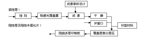
The partial laminating method of the cover layer can effectively improve the reliability of the rigid-flexible multilayer printed board and the thermal shock resistance of the metalized hole, but the cover film connected to the rigid outer layer only protrudes into the rigid area. At around /10, the positioning of non-photosensitive cover film is very difficult. Therefore, in order to reduce the difficulty in positioning the cover film during lamination, a photo-sensitive cover film may be used (imaging, since the photo resist cover film is a conventional anti-etching/electroplated dry film. In the case of small production, it may cause waste of the photosensitive cover film. It uses Target Machine for positioning during lamination. It is recommended to use one-time lamination to reduce the production process and production cost. The lamination process parameters can be General multilayer laminate process parameters are optimized).
Note: De-drilling and etchback have been described in detail in many sources and are no longer perfunctory here.
Source: Membrane Switch Technology Forum
Analysis of Rigid Flexible PCB Manufacturing Process (4)